Archives August 2023

house plan

HOUSE PLAN 31 FEET 2 INCH BY 72 FEET 2 INCH 31′-2”X72′-2” – 250 SQUARE YARDS WEST FACING HOUSE PLAN

31 FEET 2 INCH BY 72 FEET 2 INCH 31′- 2”X72′- 2” – 250 SQUARE YARDS West-bound

7Dplans.com is a web-based Stage to help you to carry on with a lovely life in a Delightful home and house plan. We are here to help you to fabricated wonderful, agreeable , esteemed and conservative home and house intend to full fill your all Fantasies. We will help you in Arranging, Construction Planning ,Electrical Planning , Plumbing Planning and Inside Planning Thinking about the significance of Vaastu for your home. Is it workable for a design to mirror the contemplations of an engineer? In the space of engineering, it’s undeniably trues that the plan cycle is generally molded by the client, their way of life, their prerequisites, and their financial plan, with little consideration given to the individual preferences of the actual draftsmen.

We have faith in making our plans stylish and completely utilitarian. With in-house creation unit, robotized and imaginative mechanical progressions and a client centered standpoint.

Engineering and Inside Plan of your house is similarly all around as significant as some other perspective inside your home. While building or renovating a space, enormous significance is given to engineering yet any space can’t be known as a fantasy home except if equivalent exertion is put towards inside arranging and planning of such space. It is this course of style where you really want to look for the assistance of the best home inside fashioners, we can truly change an engineering stunner over completely to a plan wonder.

House Plan Format

Choices OF Format PLANS WILL BE Furnished WITH .WORKING DRAWINGS CONTAIN Design DRG, ELECTRICAL and PLUMBING DRG, Entryway WINDOW DETAIL, FURNITURE Format, AND FRONT Rise (2D+3D – 2 Choices In particular)

PLOT SIZE                   LAYOUT PLAN        WORKING DRAWINGS

0-50 SQYRDS                   FREE                          9999/-

51-150 SQYRDS               999/-                           14999/-

151-300 SQYRDS             1799/-                         17999/-

301-400 SQYRDS             1999/-                         19999/-

401-500 SQYRDS             2499/-                         24999/-

HOUSE PLAN

You can Purchase nitty gritty structural working drawings for your home arrangement. You will get Building Drawings I.E Primary Drawing, Plumbing, Electrical, Furniture Format, Brickwork detail, front Height (2d+3d, 2 choices ) while purchasing Compositional Drawings. You will get 2 Choices for Floor Plan.

NOTE :-

Purchase Inside Drawings with an exceptionally ostensible expense. To purchase this drawing, send an email with your plot size and area to info.7dplans@gmail.com and one of our specialists will reach you to take the cycle forward.

Chipping away at nitty gritty drawings for your workers for hire and entryway window plan. Extra drawings like underlying drawings, electrical drawings, plumbing drawings, 2-D, and three dimensional rises.

Inside Planning work like Misleading roof Drawing, kitchen detail drawing, wood-work configuration support, furniture Drawings, and ground surface plans, are accessible at an ostensible expense of RS:- 40/sqft. To purchase this drawing, send an email with your plot size and area to info.7dplans@gmail.com and one of our specialists will reach you to take the cycle forward.

Peruse our different plans and works

construction-materials

Social Links

instagram


house plan

HOUSE PLAN OF PLOT SIZE 31 FEET 2 INCH BY 72 FEET 2 INCH – 31′-2”X72′-2” – 250 SQUARE YARDS WEST FACE HOUSE

HOUSE PLAN OF PLOT SIZE 31 FEET 2 INCH BY 72 FEET 2 INCH – 31′- 2”X72′- 2” – 250 SQUARE YARDS WEST FACE HOUSE

7Dplans.com is a web-based stage to help you to carry on with a delightful life in a Wonderful home and house plan. We are here to help you to assembled wonderful, agreeable , renowned and affordable home to full fill your all Fantasies. We will help you in Arranging, Construction Planning ,Electrical Planning , Plumbing Planning and Inside Planning Thinking about the significance of Vaastu for your home. Is it feasible for a design to mirror the considerations of a draftsman? In the space of engineering, it’s obviously true’s that the plan cycle is generally formed by the client, their way of life, their necessities, and their financial plan, with little consideration given to the individual preferences of the actual draftsmen.

We put stock in making our plans tasteful and completely utilitarian. With in-house creation unit, robotized and imaginative mechanical headways and a client centered viewpoint.

Engineering and Inside Plan of your house is similarly pretty much as significant as some other angle inside your home. While developing or restoring a space, gigantic significance is given to engineering however any space can’t be known as a fantasy home except if equivalent exertion is put towards inside arranging and planning of such space. It is this course of stylistic layout where you really want to look for the assistance of the best home inside originators, we can truly switch a structural delight over completely to a plan wonder.

Choices of format House plans will be given working drawing contain underlying drg, electrical and plumbing drg, entryway window detail, furniture design, and front rise (2D+3D – 2 choices in particular)

PLOT SIZE                   LAYOUT PLAN        WORKING DRAWINGS

0-50 SQYRDS                   FREE                          9999/-

51-150 SQYRDS               999/-                           14999/-

151-300 SQYRDS             1799/-                         17999/-

301-400 SQYRDS             1999/-                         19999/-

401-500 SQYRDS             2499/-                         24999/-

You can Purchase itemized design working drawings for your home arrangement. You will get Compositional Drawings I.E Primary Drawing, Plumbing, Electrical, Furniture Design, Brickwork detail, front Rise (2d+3d, 2 choices ) while purchasing Building Drawings. You will get 2 Choices for Floor Plan.

Purchase Inside Drawings with an exceptionally ostensible expense house plan.

To purchase this drawing, send an email with your plot size and area to info.7dplans@gmail.com and one of our specialists will reach you to take the cycle forward.

Chipping away at itemized drawings for your workers for hire and entryway window plan. Extra drawings like primary drawings, electrical drawings, plumbing drawings, 2-D, and three dimensional rises.

Inside Planning work like Misleading roof Drawing, kitchen detail drawing, wood-work configuration support, furniture Drawings, and deck plans, are accessible at an ostensible expense of RS:- 40/sq. ft. To purchase this drawing, send an email with your plot size and area to info.7dplans@gmail.com and one of our specialists will reach you to take the interaction forward.


our other social links

Instagram

BIM

What is BIM (Building Information Modeling) IN CONSTRUCTION

BIM (Building Information Modeling)

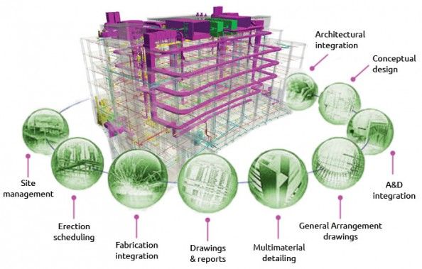
Across the world, BIM (Building Information Modeling) is an essential and, surprisingly, commanded interaction to guarantee the preparation, plan, and development of structures is exceptionally proficient and cooperative.
Peruse on to find what BIM is, the manner by which BIM is utilized, and what BIM levels mean.

What Is BIM?

BIM is an abbreviation for Building Data Displaying or Building Data The executives. A profoundly cooperative cycle permits designers, engineers, land designers, project workers,
makers, and other development experts to plan, plan, and build a construction or working inside one 3D model.
It can likewise length into the activity and the executives of structures utilizing information that structure or design proprietors approach (subsequently the Structure Data The board). This information permits legislatures, districts, and property supervisors to go with informed choices in light of data got from the model — even after the structure is built.

BIM

BIM is an acronym for Building Information Modeling or Building Information Management.

From Blueprints to CAD to BIM

BIM is an abbreviation for Building Data Demonstrating or Building Data The board.
From Outlines to computer aided design to BIM
Previously, diagrams and drawings were utilized to communicate data about a specific structure plan. This 2D methodology made it truly challenging to imagine aspects and prerequisites.
Next came computer aided design (PC Supported Plan), which assisted drafters with seeing the advantage of plans in an advanced climate. Later on, computer aided design turned 3D, which carried more reasonable visuals to outlines. Presently,
BIM (Building Data Demonstrating) is the norm — yet it is considerably more than simply a 3D model.

BIM Objects

BIM objects, the parts that make up a BIM model, are smart, have calculation, and store information. Assuming any component is changed, BIM programming refreshes the model to mirror that change.
This permits the model to stay predictable and composed all through the whole interaction so primary specialists, draftsmen, MEP engineers, fashioners, project supervisors,
furthermore, workers for hire can work in a more cooperative climate.

BIM

BIM is an acronym for Building Information Modeling or Building Information Management.

The “I” in BIM

BIM, overall, alludes to the course of all gatherings associated with the development and lifecycle the executives of assembled resources, working cooperatively and sharing information. In any case,
the genuine force of BIM lives in the “I” (Information). All of the data assembled — from origination to the end — isn’t recently put away, it’s significant.
The information can be utilized to further develop exactness, express plan expectation from the workplace to the field, further develop information move from one partner to another, diminish change requests and field coordination issues,
what’s more, give knowledge into existing structures to remodel projects later on.

How Is BIM Information Shared?

This data in a BIM model is shared through a commonly open web-based space known as a typical information climate (CDE), and the information gathered is alluded to as an ‘data model’.
Data models can be utilized at all phases of a structure’s life; from commencement to activity — and even redesigns and restorations.

Now that we’ve covered what BIM is and the way in which it tends to be utilized, we should continue on toward BIM levels.

What are BIM Levels?

Various degrees of BIM can be accomplished for different sorts of undertakings. Each level addresses an alternate arrangement of rules that exhibits a specific degree of ‘development.’ BIM levels start with 0 and go to 4D, 5D, and, surprisingly, 6D BIM. The motivation behind these levels is to measure how actually, or how much data is being shared and overseen all through the whole interaction.

So what in all actuality does each even out include, and how might you recognize which at which level you’re working? The following are brief depictions of the initial three levels and a clarification of what standards is involved at each stage.

Level 0: Paper-based drawings + zero collaboration

Level 0 BIM alludes to not working cooperatively by any means. On the off chance that you’re utilizing 2D computer aided design and working with drawings and additionally advanced prints, you can securely express you’re at level 0. Today, the greater part of the business is working over this level, albeit few out of every odd expert in the business has adequate BIM preparing and a few ventures do exclude the utilization of BIM in agreement details.

Level 1 : 2D construction drawings + some 3D modeling

Involving 3D computer aided design for idea work, however 2D for drafting creation data and other documentation, most likely means you’re working Level 1 BIM. At this level, computer aided design guidelines are figured out how to the norm of BS 1192:2007, and electronic sharing of information did from a typical information climate (CDE) for the most part overseen by the project worker. Many firms are at Level 1 BIM, which doesn’t include a lot of coordinated effort, and every partner distributes and deals with their own information.

Level 2 : Teams work in their own 3D models

Level 2 BIM starts to include a cooperative climate. BIM Level 2 was really made an obligatory necessity in April of 2016 on generally openly offered projects in the UK. France trailed behind with their own command in 2017.

At level 2, all colleagues utilize 3D computer aided design models however in some cases not in a similar model. In any case, the manner by which partners trade data separates it from different levels. Data about the plan of a constructed climate is shared through a typical document design.

At the point when firms consolidate this with their own information, they save time, decrease costs, and wipe out the requirement for adjust. Since information is shared along these lines, the computer aided design programming should be equipped for sending out to a typical document design, like IFC (Industry Establishment Class) or COB i.e. (Development Tasks Building Data Trade).

Level 3 : Teams work with a shared 3D model

BIM level 3 is significantly more cooperative. Rather than each colleague working in their own 3D model, Level 3 implies that everybody utilizes a solitary, shared project model. The model exists in a ‘focal’ climate and can be gotten to and changed by everybody. This is called Open BIM, implying that one more layer of insurance is added against conflicts, enhancing the venture at each stage.

Benefits of Level 3 are:

  1. Better 3D representation of the whole undertaking
    2. Simple coordinated effort between numerous groups and exchanges
    3. Worked on correspondence and comprehension of plan expectation
    4. Decreased adjust and corrections at each phase of the venture

Levels 4, 5, and 6: Adding in scheduling, cost, & sustainability information

BIM level 4 carries another component into the data model: time. This data incorporates planning information that helps frame what amount of time each period of the venture will require or sequencing of different parts.

Level 5 BIM adds cost assessments, spending plan investigation, and spending plan following to the data model. While working at this degree of BIM, project proprietors can follow and figure out what costs will be caused during the length of the undertaking.

Level 6 BIM data is valuable for working out the energy utilization of a structure before it’s fabricated. This guarantees that fashioners consider something beyond the forthright expenses of a resource. Level 6 BIM guarantees precise expectations of energy utilization necessities and engages partners to fabricate structures that are energy proficient and reasonable.

Benefits of Levels 4, 5, and 6 :

  1. More proficient site arranging and planning
    2. More proficient hand-offs between steps in the development stage
    3.Real-time cost representation
    4.Simplified expense investigation
    5.Reduced energy utilization over the long haul
    6.Better functional administration of the structure or construction after handover
    7.The Eventual fate of BIM
    8.Because of the reasonable advantages, BIM is setting down deep roots.
    It has characterized objectives and targets that are plainly advantageous to every one of the individuals who manage the levels. Without a doubt, the fate of development will be significantly more profoundly cooperative and computerized.
    As BIM turns out to be progressively more complex, 4D, 5D, and, surprisingly, 6D BIM will begin to have an impact simultaneously.
    Moreover, all over the planet, there is an endeavor to lessen squander in development. Quite a bit of this is credited to production network shortcomings, conflicts, and modifying. By working cooperatively in a BIM ecological of this turns out to be substantially less possible, making way for a superior tomorrow.

    As we plan ahead, we see gigantic potential. BIM is just the start of what’s conceivable with current development instruments and innovation. At the point when BIM is layered with the standards of Associated Development, the fantasy of BIM turns into a reachable reality.

    Trimble is combining efforts with industry pioneers in design, designing, and development to scrutinize Associated Development in The Incomparable Library docuseries. Over a progression of episodes,
    we will carefully change the Library of Celsius into a cutting edge office.


Our other social links

Instagram 

other blogs and works

construction-materials

Vaastu-shastra


What Is Bill Of Quantities (BOQ)?

What Is Bill Of Quantities (BOQ)?

A Bill of Quantities (BOQ) is a report made by an amount assessor or cost specialist that contains data on the amount of materials, work , and their costs in a development project. The Bill of Amounts is a fundamental piece of the delicate. Without a reasonable Bill of Amounts, a delicate is fragmented. It by and large incorporates data, for example, the extent of work, the expense of work, the materials used, the quantity of laborers utilized, etc. Project workers can utilize this data and information to cite rates for their particular work. A Bill of Amounts guarantees that the task moves along as planned and without inconveniences. A Bill of Amounts is some of the time utilized as a kind of perspective for future ventures. After a development, plan has been finished and determinations have been made, BOQs help in cost calculation. It goes about as a significant connection between partners, experts, architects, and project workers.

Purposes of Bill of Quantities:-

  1. To make the offering system more uniform.
    2. For laying out a strategy for esteeming the task that is both straightforward and definite.

    3. To give an exhaustive portrayal of the work and its rates, as well as the general expense.

    4. To help amount assessors in guaranteeing that singular project workers have documented legitimate tenders that conform to the details.

Significance of Bill of Quantities (BOQ):-

  1. Quite possibly of the most fundamental report in the development business is the bill of amounts.

    2. A Bill of Amounts offers a project worker a reasonable image of the entire venture about which worker for hire needs to deal with it.

    3. BOQ gives a base to the clients for esteeming, looking at tenders, and contrasting agreements.

    4.It’s expected for setting up the workers for hire’s last bill.

General Format of a BOQ:-

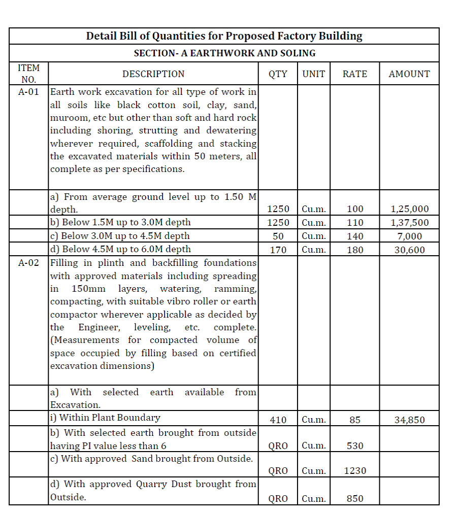
BOQ is ready in plain structure which incorporates Thing nos., Thing portrayal, Amount, Unit of estimation, Unit rate, Sum, and Comments (if any). BOQ’s fundamental configuration is as per the following:

Bill Of Quantities

Bill Of Quantities

How to Prepare Bill of Quantities :-

There are three essential stages to making a BOQ. Coming up next are the subtleties:

1. Description of work

This is the first and most significant stage in making a BOQ. The work to be done is point by point and written in basic words with the goal that the worker for hire knows precisely exact thing the person is obligated for.

2. Amount take-off

The amount of work is determined and taken off once the work is portrayed. It gives an exact gauge of the amount of work that a worker for hire will be liable for. How much work is estimated in Cu. m, Sq. m, rm, foot, and different units according to particulars.

3. Rates per unit of work

The last stage in making a BOQ is portraying the paces of work things per unit. Every thing’s rates are determined. Market overview, current rates, timetable of rates (SOR), and different rules are thought of. Ultimately, the all out amount of work is duplicated by the unit pace of the thing of work to compute the aggregate sum for a particular thing of work.

Common Errors in Bill of Quantities Preparation :-

1.Error in computing the amount of work and the paces of work things.

2.Inaccurate suppositions about specific work things.

3.The inaccurate estimation is taken.

4.Work things can be counted two times.

5.Taking trivial things to work.

6.Taking trivial things to work.


Our other social links

Instagram 

other blogs and works

construction-materials

Vaastu-shastra


RULE FOR 25% COMMERCIAL APPROVAL IN HUDA OR TOWN PLANNING TCP HARYANA

TOWN PLANNING TCP HARYANA

Town Planning TCP , Reference is drawn towards the notice dated 06.02.2008 gave by this
Office, with respect to consent for non-irritation proficient consultancy administrations such
as Specialists (without nursing home), Attorneys, Expense Experts, Draftsmen and Town Organizers
(without studio), Worker for hire Experts, Contracted Bookkeepers, Organization Secretaries,
Property Advisors, Ayurvedic and Homeopathic Expert, Specialist, Clinical
Analyst and Local escorts. These exercises are allowed to the degree of 25% of the
developed region of the structure or up to 50 sq. miter, whichever is less in Private Plots. The
same was subsequently consolidated in Part 6 of Haryana Construction regulation 2017 (HBC).
While, it has been seen that the overall population isn’t greatly familiar
with the said guidance/arrangements of HBC-2017 and keeping in mind that making a move against such
infringement in neighborhoods, the violators are not made mindful of similar by the field workplaces.
Appropriately, to resolve this issue, it is therefore requested that all DTPs in their
separate Locale will guarantee that the overall population is sharpened about the guidelines,
so they might apply for earlier authorizations according to arrangements of HBC-2017.

DATED :- 18/08/2023                                                                      End St. No. Misc-2339 (Free Vol-I)/2023/27089-91


Our other social links

Instagram 

other blogs and works

construction-materials

Vaastu-shastra


BBS

What is the Bar Bending Schedule (BBS) of TMT Bar

What is the Bar Bending Schedule (BBS) of TMT Bar?

Building a home requires a few variables to be thought about to obtain the best outcome. Before you start the development of your home you really want to have the ideal preparation, exact assessment and best quality structure materials and BBS

In development, TMT Bar is one of the superb materials that make your home

Heat proof
Seismic tremor Safe

Consequently, it is fundamental to pick the best quality TMT Bar that has the ideal equilibrium of solidarity and adaptability and makes your home never-ending. TMT Bars are generally utilized for their flexibility and bendability. TMT Bar is a cutting edge innovation that is utilized in a wide range of development. The Thermo Mechanical Treatment brings about areas of strength for a martensite layer on the external side that outcomes in the rigidity to it and the delicate ferrite-pearlite internal center makes it exceptionally malleable. TMT Bars are notable for their bendability.

Here we will examine the Bar Bowing Timetable (BBS) that will assist with improving on the steel bar assessment for development and benefit of it.

Bar Bowing Timetable or Timetable of Bar is performed relying on the supported substantial work thing. Bar twisting plan sums up each of the needed specifics of bars – measurement, the state of bowing, length of each and every bowed and straight part, points of twisting, the general length of each and every bar, and the quantity of each kind of bar. This reality is a choice help with setting up a gauge of amounts.


BBS

What is Bar Bowing Timetable?

Estimation of the all out amount of TMT Steel Bar expected for building development is named a Bar Twisting Timetable. Steel Bar support in substantial designs in this way the development construction can endure the strain. How much is TMT Bar expected to develop your home? What sort of steel bar is best for development? The amount TMT Bar is expected in RCC? This large number of inquiries can be served during Bar Twisting Timetable (BBS).

Adjustment in Bar Twisting Timetables

The development business quickly different over the most recent couple of many years. Already three to four-story structures were viewed as skyscraper however with the quick development in the development business, we could see 100+ story structures all the time.

As per the old development strategy utilizing four steel bars in a segment was standard yet presently we are utilizing 15+ steel bars in the line in light of burden examination. The ascent in total populace requested more spaces in little regions.

Bar Bending Schedule (BBS)

Learning the rudiments prior to managing BBS is significant

Particular                                                                      Result

Standard Length of TMT Steel Bar =                             12M or 40’
Weight of bar for length                    =                             1m (Dia of Bar)*2/162
Steel Density                                        =                             7850 Kg/m3

Significant focuses to be noted for Bar Bowing Timetable

  1.  TMT Steel Bars ought to be held together in a gathering that can be distinguished for each underlying unit and the rundown ought to be very much circulated for each floor
  2. Bars ought to be in numeric request numbers
  3.  Each bar in the group ought to be named appropriately with the length, size and state of the bar
  4.  In the bar bowing cutting timetable cutting length and twisting length estimation ought to be done independently.
    Significant Use of Bar Twisting Timetable


Significant Use of Bar Twisting Timetable

  1. Bar Bowing Timetable (BBS) assists with deciding the amount of steel expected in the development of your home. This assists with getting a precise assessment of steel
    2. When the computation of cutting and twisting is done it lessens the wastage of steel and it becomes monetary
    3. When you get the support drawings, cutting and twisting should be possible at the stockroom before transportation. It speeds up development and the transportation cost additionally lessens.
    4. Prior to putting the substantial assuming that the twisting and cutting length of TMT Steel bars are estimated it becomes more straightforward for site engineers.


Our other social links

Instagram 

other blogs and works

construction-materials

Vaastu-shastra


What are Stirrups in RCC and Types of Stirrups ?

What are Stirrups in RCC?

We have alluded to this as equal ties during our examinations. Stirrups are closed circle bars connected at common traverses in point of support backing to stand firm on the bars in circumstance.
Flat ties are used to stand firm on the balance of the help in a section without disturbing the significant space. Both are something almost identical and simply shift from their circumstance.
If it is placed in a segment it is known as equal ties. If it is set in a point of support it is known as stirrups. The components of both differentiation for point of support and area.
Generally the stirrups are arranged in a rectangular or square shape yet on occasion, it may be given in indirect or slantingly.

Why are the Stirrups & Ties provided in Beam and Column reinforcement?

It stands firm on the rebars in circumstance and thwarts deformation. It positions the posts in a comparative alignment. To secure the bar and portion from the catching and shear disillusionment.
The stirrups are contradicting the bars under tension or versatile force.The isolating of stirrups will be different considering the arrangement for both segment and bar.
The base separating is 100mm and the best is 250mm, considering the estimation and amounts of the bar.

Types of Stirrups

The going with sorts of stirrups are by and large used in help and in a couple of outstanding cases the designer changes the stirrups considering the arrangement essential.

Single Legged Stirrups (Open Stirrup)
Two-Legged or Double legged Stirrups (Closed)
Four-Legged Stirrups (Closed)
Six-Legged Stirrups (Closed)
Circular Stirrups (Open Stirrup)
Helical Stirrups (Open Stirrup)

Single Legged Stirrups

Single-leg stirrups have only occasionally been used considering the way that they are by and large used while limiting only two shafts.

Single Legged Stirrups

Single Legged Stirrups

Two-Legged Stirrups


Ordinary and comprehensively using stirrup type id Two-legged stirrups. To provide this stirrup with a base 4 number of the shaft is required.

Single Legged Stirrups

Single Legged Stirrups

Four Legged Stirrups

Single Legged Stirrups

Single Legged Stirrups

Six Legged Stirrups

Single Legged Stirrups

Single Legged Stirrups

Circular Stirrups

Circular stirrup is used when the part is a round shape.

Circular Stirrups

Circular Stirrups

Helical Stirrups

By and large it is used in load sections and moreover for the pile foundation the stirrup can use either Helical or indirect.

Helical Stirrups

Helical Stirrups

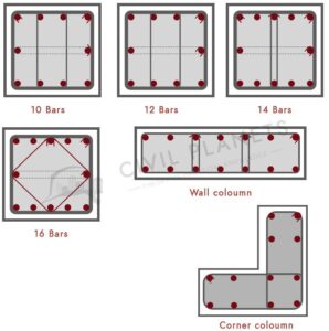
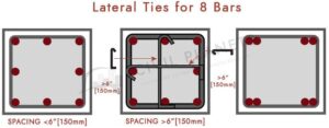
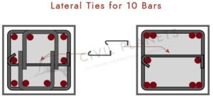
Lateral Ties

These types of lateral ties have been used when the number of rods was increased.

Such equal ties have been used when the amount of shafts was extended.

Lateral Ties

Lateral Ties

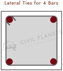
Ties for 4 Bars

Lateral Ties for 4 Bars

4 Bars

Lateral 8 Bars

Lateral Ties for 8 Bars

Lateral  8 Bars

Lateral Ties for 10 Bars

Lateral Ties for 10 Bars

Ties for 10 Bars


Our other social links

Instagram 

other blogs and works

construction-materials

Vaastu-shastra

Chandigarh secretariat ,history, master plan

Chandigarh secretariat ,history, master plan

Chandigarh

Chandigarh, Chandigarh secretariat ,history, master plan the fantasy city of India’s most memorable Top state leader, Sh. Jawahar Lal Nehru was arranged by the well known French modeler Le Corbusier. Beautifully situated at the lower regions of Shavlik’s, it is known as perhaps of the best examination in metropolitan preparation and current design in the 20th hundred years in India. Chandigarh became representative of the recently autonomous India. The establishment stone of the city was laid in 1952. The city is notable for its engineering and plan by draftsmen like Le Corbusier, Pierre Jeanerette, Jane Drew, and Maxwell Fry.

History:-
Chandigarh secretariat ,history, master plan

During the 50s Le Corbusier was approached to foster the arrangement of Albert Mayer. Mayer began a few years before with the principal Ground breaking strategy for Chandigarh and gotten the Clean conceived American planner Matthew Novicki, who passed on in a plane accident in 1950. The public authority officials of Punjab jumping all over the chance to track down another group of engineers and town organizers.

Le Corbusier was utilized for the All-inclusive strategy and the Capital structures and worked from 1951 until his passing in 1965 on the development of the city. Pierre Jeanerette, his cousin and accomplice was employed as the site planner. Maxwell Fry and Jane B. Drew worked for around three years on the undertaking and afterward left because of their commitment somewhere else. In 1965 M.N. Sharma took over from Pierre Jeanerette as the primary Indian Boss Engineer of the Venture and after the rearrangement of the Province of Punjab in 1966 and the foundation of Association Region, Chandigarh, he was designated as Regulatory Secretary of the Branch of Design in the Chandigarh Organization.

End-all strategy:-

The Ground breaking strategy by Le Corbusier was extensively like the one arranged by Albert Mayer and Mathew Nowicki, then again, actually the state of the city plan was changed from one with a bending street organization to a rectangular shape with a field design for the quick traffic streets, other than diminishing its region for the explanation of economy. The city plan was considered as a post-war ‘Nursery City’ wherein vertical and elevated structures were precluded, keeping in view the financial circumstances and residing propensities for individuals.

Every one of the fundamental streets were fixed, the aspects and association of the superblocks were reformatted, a total order of course was laid out, the terminology was changed, and the Capital “head” was solidly situated set up.

The illustration of a person was being utilized in the arrangement – the ‘head’ contained the capital mind boggling, the ‘heart’ the business place, and the ‘arms’, which were opposite to the principal pivot, had the scholar and recreation offices. The arrangement integrated Le Corbusier’s standards of light, space and plant life. What had been named an “Metropolitan Town” in Mayer’s arrangement, Le Corbusier renamed a “Sectors”.

Sectors Chandigarh secretariat:-

Le Corbusier isolated the city into various Areas. Every Area or the neighbored unit, is very like the customary Indian ‘Mohalla’, and measures 800 meters by 1200 meters, covering 250 sections of land of region. The area highlighted a green strip running north to south, separated by a business street running east to west. The roads were coordinated in a lessening pecking order and marked V1 through V8: V1: blood vessel streets that interface one city to another, V2: metropolitan, city streets, V3: vehicular street encompassing an area, V 4: shopping road of an area, V5: circulation street wandering through an area, V6 private street, V7: passerby way, V8: cycle track. Every Area is encircled by V2 or V3 streets, without any structures opening onto them and intended to be independent, with shopping and local area offices inside sensible strolling distance.

The instructive, social and clinical offices are spread all around the city, notwithstanding, significant organizations are situated in Areas 10, 11, 12, 14 and 26. The two Universities, the Ecole d’Art et d’Architecture from 1950-1965 are significant structures by Le Corbusier. Their studios and homerooms are gathered around inside yards. The structures are seriously arranged north and south so that light enters from the north. The lobbies are isolated by low parcels. Le Corbusier established that these school edifices and the Exhibition hall must be worked of the ruddy earthy colored block that is normal in India, or if nothing else confronted with this block; along these lines, he tried to forestall structures inside sight of the State house from drawing in an excess of consideration from his distinction structures of cement.

The modern region contains 2.35 sq km, put away in the Ground breaking strategy for non-contaminating, light industry on the super southeastern side of the city close to the rail route line, as distant from the Instructive Areas and Legislative hall Complicated as could really be expected.

Sector 17/City Centre and Chandigarh secretariat :-

The downtown area (Area 17) is the core of Chandigarh’s exercises. It includes the Between State Transport End, March Ground, Area Courts, and so forth on one hand, and a huge business and shopping centre on the other. The 4-story substantial structures house banks and workplaces above and display areas/shops at the ground level with wide common concourses. The Neelam piazza in the middle has wellsprings with light and water highlights. Area 34 is another recently evolved business area.

The streets were planned and situated so that more often than not during the day, they are under shadow. There are immense stopping regions for the business zones so the Stopping issues don’t make devastation on the primary streets.

Le Corbusier called it Les Sept Voies de Course, or 7Vs. The reasoning of his arranging was the engine vehicle. “From his initial examinations in urbanism, Le Corbusier had distinguished the engine vehicle as the focal variable of current town arranging. His underlying, fundamentally stylish, semi Futurist reaction to the engine vehicle and to fast development in the urban communities had, by 1950, transformed into a hypothetical answer for the issues of present day traffic – – a reviewed arrangement of dissemination, from crossing mainlands to strolling to the front entryway. The 7 Versus act in the town plan as the circulation system, the lymph framework and the respiratory framework act in science. These frameworks are very levelheaded, they are unique in relation to one another, and there is no disarray between them, yet they are as one … It is for us to gain from them when we are sorting out the ground that lies underneath our feet. The 7Vs are at this point not the vile instruments of death, however become a coordinated pecking order of streets which can manage present day traffic flow’.” [Prasad Sunand, 1987].

Le Corbusier had confidence as one by utilizing the Plan standard of Balance. He planned bunches of lodges. With every unit comprising of a basic game plan of a veranda, two rooms, a kitchen, an outside water wardrobe, and an “Indian-style” latrine, every unit had outdoors space in front and back as expansions of the house and was conquered by an optional parasol rooftop to keep it cool. ” It is a similar standard which was utilized in the huge loft obstructs (the Join at Marseilles for instance)”, Le Corbusier noted, “where on the 17 stories the condos are touching and of a similar design”.

Chandigarh was Le Corbusier’s chance to satisfy his thoughts, and he obviously projected onto India. Le Corbusier, nonetheless, couldn’t execute his full picture of a city. Other than the End-all strategy, the genuine lodging of the city was not what he maintained that it should be. Le Corbusier’s vision is contained in the chronicled record of a first gathering in 1950. Le Corbusier authoritatively reported to the remainder of the group: “My piece of the work will then, at that point, fabricate a “Block of Building”, a “Home Solidarity” which as of now exists, that can be probed the spot and will be one of the many “Staying Solidarities” which you will work around there. I might want to develop a couple of public structures to utilize my own insight”.

“Abiding Solidarity” is the English interpreter’s strict interpretation of “Join d’ Habitation”. Le Corbusier needed to see more Join in Chandigarh. His renowned units were models of incorporated vertical living. Taken clear off the ground plane, they were intended to accentuate their relationship with the sun and the sky and their independence from the beginning. Le Corbusier couldn’t understand this kind of Join together, enormous loft blocks in Chandigarh.

Chandigarh secretariat :-

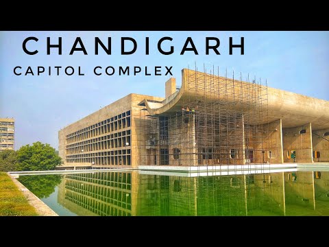
The Secretariat (1953) is an extremely enormous structure and 254 meters in length and 42 meters high houses the ecclesiastical chambers and every clerical office. The Services are gathered in a focal structure, Block 4, one of the six clerical blocks, each isolated from the following by an upward development joint expanding the full level of the structure.

The outside is of unpleasant concrete, in other words, the vertical brise-soleil, the railings and the flat brise-soleil, the acroterium which contrasts the sky leaving noticeable the housetop facilities which are to be utilized for a club and for gatherings. The two enormous slopes before and behind the structure, serve all floors and are moreover in unpleasant cement. They offer an exceptionally overwhelming arrangement of flow (morning and night) for the 3.000 workers.

Vertical course is guaranteed by batteries of ele­vators matched by a flight of stairs running in the two headings encased in an upward spine ascending from ground level to the culmination of the rooftop. Harsh cement comparatively covers the two end walls drawing out the impact of the standard sheet-metal formwork.

The block of ecclesiastical workplaces has been the object of extremely cautious examination as to the sculptural help given to harsh cement by the impact of different kinds of brise-soleil. The unpleasant cement again mediates in the fenestration of the two primary veneers: more than 10.000 units of an exceptional plan – one bolster type 27×7 cm in segment and 366 cm high comprise the “undulatory coating”. This concerns an appli­cation here of the Modular which allows the extending of a cloak of glass broadening the whole length and level of the structure, hindered by components called “ventilators” which contain a shade of sheet-metal turning upward from floor to roof across an opening of 43 cm and equipped for being opened to any ideal width, from 1 millimeter up to 43 centimeters; covered, what’s more, by a drape of copper mosquito-netting. Along these lines, a colossal setting aside of cash and upkeep was acknowledged with this fenestration, when contrasted and wood or metal.

The Modular has; directed the essential segment of the workplace types in the structure (3.66 meters of level under the transoms) allowing a harmonization of the levels of the clerical chambers by a multiplying of extents and has given to blocks 5 and 6, which lay on pilotis at park level, a play of level of genuine persuasiveness (entrance level to the Pastors’ structure, level of ecclesiastical workplaces and the pilotis of blocks 5 and 6).

The 3.000 representatives of the Secretariat show up by transport, bike, or by walking, and (have various gets to relying on whether the course they take from the city is the “Avenue of the Waters” or the “Valley of Relaxation”. The auto network is settled in all through the recreation area of the Legislative center, in this way barring vehicles from the visual field of the easygoing carriage in the recreation area.

Legislative Assembly:-

The Parliament or Official Get together (1955) was planned as an enormous box with the entry colonnade on one side, substantial wharfs on the other, and a tedious example on the veneer. Sculptural structures on the rooftop, a sensational ‘channel’ top light over the Gathering, and a shifted pyramid over the Senate chambers finished the organization.

The Gathering Corridor has a square arrangement. The Gathering chamber, as an exaggerated shell, is encircled by stately space. This flow space is arranged as a faintly lit, triple-level, segmented lobby for casual gatherings and conversations. The side of the lobby confronting the high court has an incredible patio and eight flimsy docks. These wharfs outline a perspective on looks at the Shavlik Slopes.

A stylized turning entryway is set in a toppy turvy sound of the porch. Le Corbusier was roused by the type of the cooling pinnacles of a power station close to Ahmedabad. The modeler planned the exaggerated shell of the Gathering chamber with a base breadth of 39.6m. This shell is 38m and ends in a diagonal segment with a metallic structure at the top. This system coordinates the interaction of normal and counterfeit lighting, ventilation, and acoustics.

The exaggerated shell is just 15cm thick, which helped in lessening the expense and the heaviness of the construction. The Get together chamber has a seating limit of 252 people. Extra exhibitions are accommodated women, columnists, and authorities. Acoustical treatment has been given to the Gathering Chamber to adjust and control the sound levels by giving sound-engrossing boards in brilliant varieties and irregular curvilinear shapes. The Committee chamber, with a limit of 70 seats is delegated by a pyramid, which concedes light from the north into its inside. A woman’s exhibition with 90 seats, a men’s display with 104 seats, and a press exhibition with 24 seats are likewise given in this chamber. Flights of stairs, lifts and slopes give different method for dissemination and admittance to various levels of the structure. The development of the whole design is in uncovered built up concrete.

The High Court :-

The High Court (1952) has been being used since Walk 1956. The methodologies have not at this point been ready: two of the three bowls of water have not yet been uncovered before the Royal residence; the outside polychromic is charged up, for the occasion, on the central exterior, simply by the brise- soleil of the Courtrooms; the three arches of the excellent entry porch, covered with a concrete delivering, are to be painted-one green, the other white, and the third in red-orange, both left and right walls to be painted dark.


Our other social links

Instagram 

other blogs and works

construction-materials

Vaastu-shastra

HOUSE PLAN

HOUSE PLAN OF PLOT SIZE 33 FEET BY 25 FEET = 33’X25′ = 92 SQUARE YARDS PLOT SIZE NORTH FACING

NORTH FACING HOUSE PLAN

7Dplans.com is a web-based Stage to help you to carry on with a delightful life in a Lovely home and House plan. We are here to help you to fabricated lovely, agreeable , esteemed and conservative home to full fill your all Dreams. We will help you in Planning, Structure Planning ,Electrical Planning , Plumbing Planning and Inside Planning Thinking about the significance of Vaastu for your home. Is it workable for a design to mirror the contemplations of a planner? In the space of engineering, it’s obviously true that the plan cycle is generally formed by the client, their way of life, their prerequisites, and their spending plan, with little consideration given to the individual preferences of the actual designers.

We put stock in making our plans tasteful and completely utilitarian. With in-house creation unit, mechanized and imaginative mechanical progressions and a client centered viewpoint.

Engineering and Inside Plan of your house is similarly all around as significant as some other angle inside your home. While building or renovating a space, huge significance is given to engineering yet any space can’t be known as a fantasy home except if equivalent exertion is put towards inside arranging and planning of such space. It is this course of stylistic layout where you really want to look for the assistance of the best home inside fashioners, we can truly change a structural delight over completely to a plan wonder.

Choices OF Design PLANS WILL BE Furnished WITH .WORKING DRAWINGS CONTAIN Construction DRG, ELECTRICAL and PLUMBING DRG, Entryway WINDOW DETAIL, FURNITURE Format, AND FRONT Rise (2D+3D – 2 Choices In particular)

PLOT SIZE                   LAYOUT PLAN        WORKING DRAWINGS

0-50 SQYRDS                   FREE                          9999/-

51-150 SQYRDS               999/-                           14999/-

151-300 SQYRDS             1799/-                         17999/-

301-400 SQYRDS             1999/-                         19999/-

401-500 SQYRDS             2499/-                         24999/-


HOUSE PLAN


You can Purchase point by point engineering working drawings for your home arrangement. You will get Building Drawings I.E Primary Drawing, Plumbing, Electrical, Furniture Format, Brickwork detail, front Height (2d+3d, 2 choices ) while purchasing Compositional Drawings. You will get 2 Choices for Floor Plan.

NOTE :- Purchase Inside Drawings with an extremely ostensible expense. To purchase this drawing, send an email with your plot size and area to info.7dplans@gmail.com and one of our specialists will reach you to take the interaction forward.

Dealing with nitty gritty drawings for your project workers and entryway window plan. Extra drawings like primary drawings, electrical drawings, plumbing drawings, 2-D, and three dimensional rises.

Inside Planning work like Misleading roof Drawing, kitchen detail drawing, wood-work configuration support, furniture Drawings, and ground surface plans, are accessible at an ostensible expense of RS:- 40/sqft. To purchase this drawing, send an email with your plot size and area to info.7dplans@gmail.com and one of our specialists will reach you to take the cycle forward.


Our other social links

Instagram 

other blogs and works

construction-materials

Vaastu-shastra

OPEN WEST FACING HOUSE PLAN

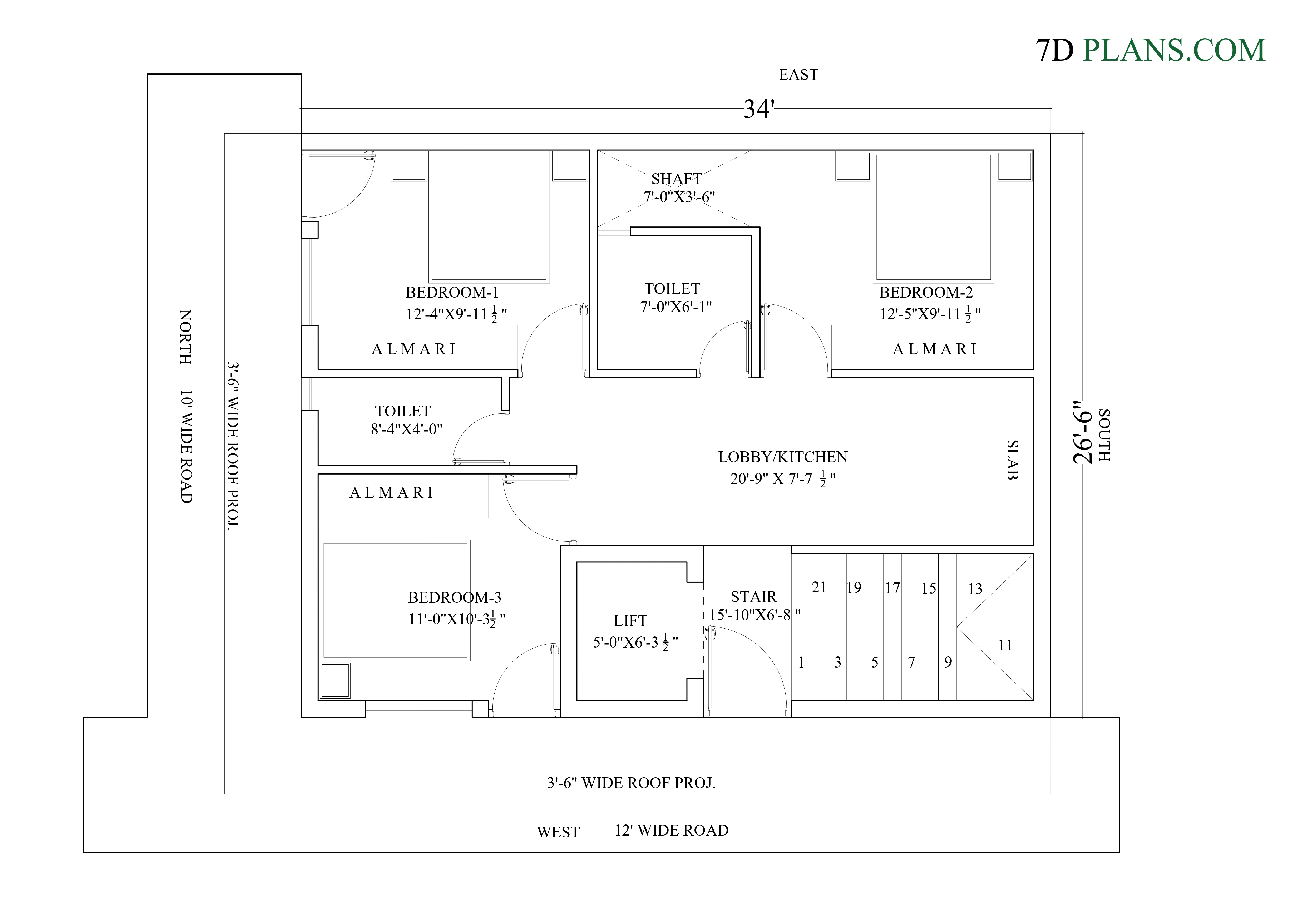
HOUSE PLAN OF 34 FEET BY 26 FEET 6 INCH 34’X26′-6” 100 SQUARE YARDS PLOT 2 SIDE OPEN WEST FACING

OPEN WEST FACING HOUSE PLAN

7Dplans.com is a web-based Stage to help you to carry on with a delightful life in a Lovely home and house plan. We are here to help you to assembled wonderful, agreeable , renowned and practical home to full fill your all Dreams. We will help you in Planning, Structure Planning ,Electrical Planning , Plumbing Planning and Inside Planning Thinking about the significance of Vaastu for your home. Is it workable for a construction to mirror the considerations of a modeler? In the space of engineering, it’s undeniably true that the plan cycle is to a great extent formed by the client, their way of life, their prerequisites, and their spending plan, with little consideration given to the individual preferences of the actual draftsmen.

We have confidence in making our plans stylish and completely utilitarian. With in-house creation unit, robotized and imaginative mechanical headways and a client centered viewpoint.

Engineering and Inside Plan of your house is similarly just about as significant as some other viewpoint inside your home. While building or renovating a space, massive significance is given to engineering however any space can’t be known as a fantasy home except if equivalent exertion is put towards inside arranging and planning of such space. It is this course of stylistic layout where you want to look for the assistance of the best home inside planners, we can really switch a structural stunner over completely to a plan wonder.

2Choices OF Design PLANS WILL BE Furnished WITH .WORKING DRAWINGS CONTAIN Construction DRG, ELECTRICAL and PLUMBING DRG, Entryway WINDOW DETAIL, FURNITURE Format, AND FRONT Height (2D+3D – 2 Choices In particular)

PLOT SIZE                   LAYOUT PLAN        WORKING DRAWINGS

0-50 SQYRDS                   FREE                          9999/-

51-150 SQYRDS               999/-                           14999/-

151-300 SQYRDS             1799/-                         17999/-

301-400 SQYRDS             1999/-                         19999/-

401-500 SQYRDS             2499/-                         24999/-


OPEN WEST FACING HOUSE PLAN


You can Purchase definite structural working drawings for your home arrangement. You will get Engineering Drawings I.E Underlying Drawing, Plumbing, Electrical, Furniture Design, Brickwork detail, front Height (2d+3d, 2 choices ) while purchasing Structural Drawings. You will get 2 Choices for Floor Plan.


Note:-

Purchase Inside Drawings with an extremely ostensible expense. To purchase this drawing, send an email with your plot size and area to info.7dplans@gmail.com and one of our specialists will reach you to take the cycle forward.

Chipping away at point by point drawings for your workers for hire and entryway window plan. Extra drawings like underlying drawings, electrical drawings, plumbing drawings, 2-D, and three dimensional heights.

Interior Designing  work like Misleading roof Drawing, kitchen detail drawing, wood-work configuration support, furniture Drawings, and ground surface plans, are accessible at an ostensible expense of RS:- 40/sq. ft. To purchase this drawing, send an email with your plot size and area to info.7dplans@gmail.com and one of our specialists will reach you to take the cycle forward.


Our other social links

Instagram 

other blogs and works

construction-materials

Vaastu-shastra